


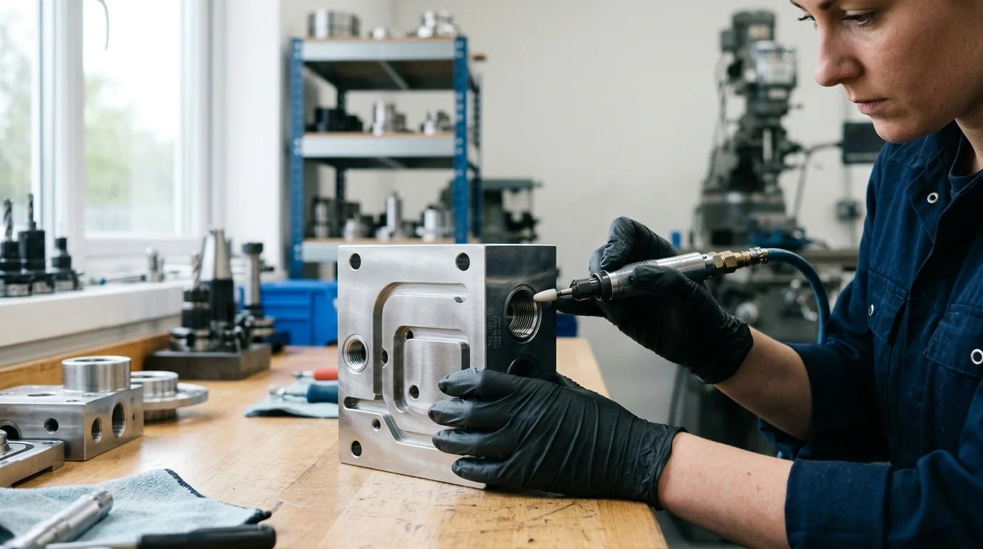
In hydraulic equipment, a surface that looks smooth can still destroy seals, leak pressure, and shorten machine life. Components working at 350 to 700 bar depend on controlled micro-geometry: roughness, valley depth, bearing area, roundness, straightness, hardness, and coating thickness all influence how reliably oil films form and how long seals survive. This article explains why finishing is a strategic manufacturing control point, not a cosmetic step, and how specifications such as Ra, Rz, Rmr, and coating thickness translate into field performance. It also highlights where precision grinding, polishing, and automated finishing help reduce variation, prevent premature failures, and support longer hydraulic system lifecycles.
Why Hydraulic Component Finishing Is a Strategic Control Point
Hydraulic systems operating at extreme pressures—often ranging from 350 to 700 bar (5,000 to 10,000 psi)—rely on precision-engineered components to maintain volumetric efficiency and safety. In these demanding environments, hydraulic component finishing transcends mere aesthetic enhancement; it acts as a strategic control point governing the entire system's reliability and lifecycle.
Defining Finishing Beyond Surface Appearance
In advanced fluid power systems, finishing is defined by precise micro-geometric parameters rather than simple visual reflectivity. Engineers must control the bearing area ratio (Rmr), valley depth (Rvk), and core roughness (Rk) to ensure optimal fluid retention and load distribution. A cylinder bore may appear smooth to the naked eye but still possess microscopic peaks that act as abrasive cutting tools against elastomeric seals. By managing the Abbott-Firestone curve characteristics, manufacturers establish a functional surface that sustains a microscopic hydrodynamic fluid film, preventing dry friction during high-cycle actuation.
Failure Modes Linked to Poor Finishing
Inadequate surface finishing accelerates several catastrophic failure modes. When peak roughness (Rp) exceeds acceptable thresholds, components experience rapid seal wear, leading to internal bypass leakage and a corresponding drop in system pressure. For instance, a surface roughness variance of just 0.2 micrometers (Ra) beyond the specified limit can reduce dynamic seal life by up to 30%. Furthermore, deep surface scratches or improper cross-hatch angles can induce micro-dieseling—a phenomenon where trapped air bubbles ignite under pressure, causing localized thermal degradation and pitting on the cylinder walls. Managing these parameters is essential for mitigating premature warranty claims and catastrophic field failures.
Key Specifications for Reliable Hydraulic Component Finishing
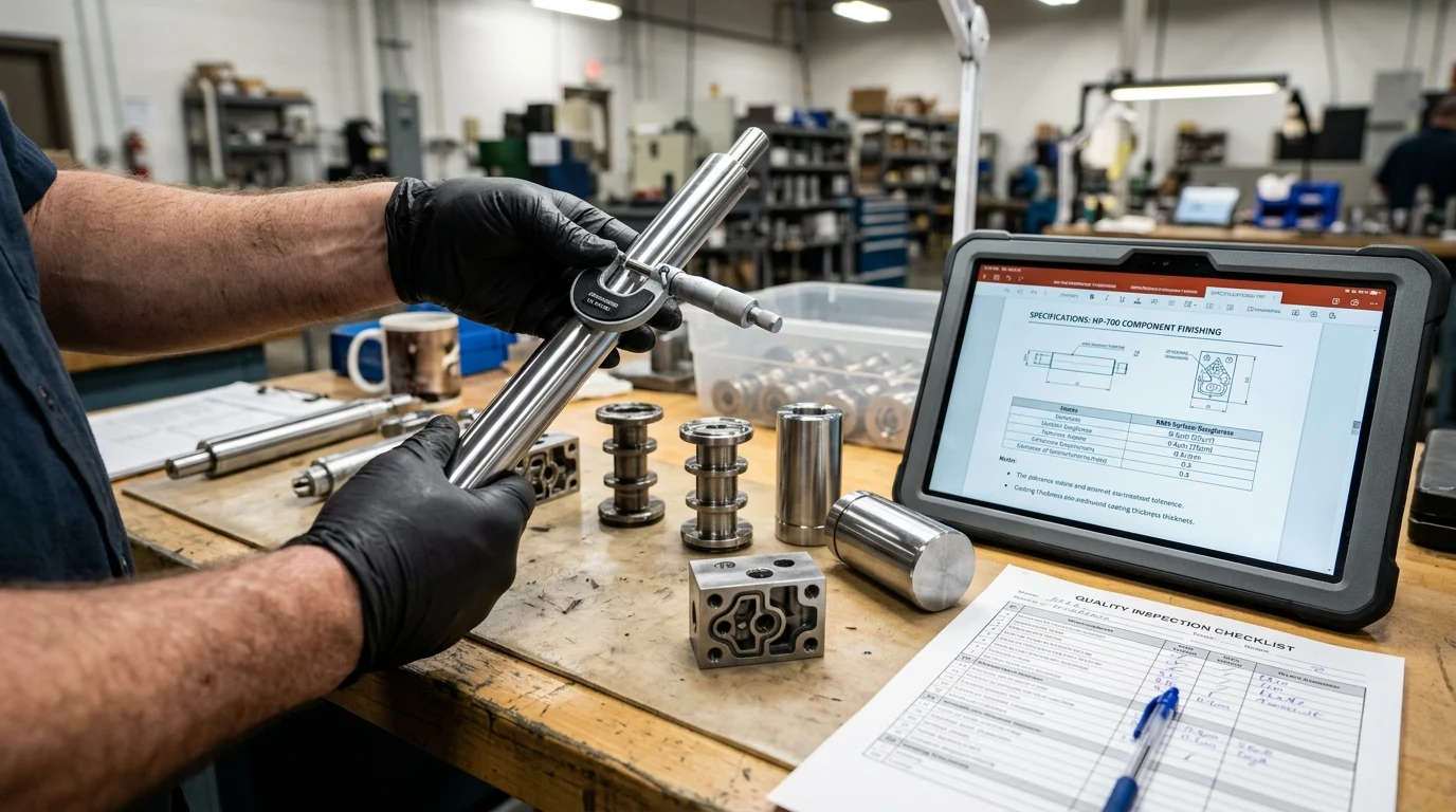
Translating performance requirements into actionable manufacturing data requires rigorous specification. Hydraulic component finishing relies on tight geometric and material controls to ensure interchangeability and predictable wear characteristics over millions of duty cycles.
Surface Roughness, Roundness, and Straightness
Surface roughness is typically specified using Ra (average roughness) and Rz (mean peak-to-valley height), with typical hydraulic cylinder bores requiring an Ra between 0.1 and 0.4 micrometers. However, roughness alone is insufficient without stringent geometric tolerances. Roundness (circularity) and straightness are critical to prevent uneven radial loads on piston seals. High-performance servo-hydraulic cylinders frequently demand roundness tolerances tighter than 0.005 mm and straightness deviations below 0.01 mm per meter of stroke. Deviations beyond these thresholds introduce localized stress concentrations, leading to asymmetric seal extrusion and fluid bypass.
Material, Hardness, and Coating Requirements
The interaction between the base material, surface hardness, and applied coatings dictates the component's resistance to galling and corrosion. Piston rods are commonly induction hardened to 50-55 HRC before receiving a hard chrome plate, which elevates the surface hardness to approximately 65-70 HRC. In highly corrosive environments, alternative coatings such as High-Velocity Oxygen Fuel (HVOF) applied tungsten carbide or nickel-chromium are specified. These coatings must be finished to precise thicknesses—often requiring post-coating grinding to maintain a final layer thickness of 20 to 50 micrometers—ensuring the coating neither flakes under flexural stress nor compromises the dimensional tolerance of the shaft.
Drawings, Tolerances, and Acceptance Criteria
Engineering drawings must unambiguously define finishing requirements, utilizing standardized metrology frameworks. Acceptance criteria should reference international standards, such as those published by the International Organization for Standardization, to define the exact evaluation length and filtering methods for surface profilometry. Tolerances must account for the accumulation of variances from pre-machining to final polishing. A robust drawing specifies not only the target Ra and Rz but also the required cross-hatch angle—typically between 30 and 45 degrees—to optimize lubricant retention without creating spiral leakage paths.
Comparing Hydraulic Component Finishing Methods
Achieving the stringent tolerances required for fluid power applications necessitates selecting the appropriate abrasive machining process. Each finishing method imparts a distinct surface topography, directly influencing the tribological behavior of the mating components.
Honing, Superfinishing, Grinding, and Polishing
The primary finishing methods—honing, superfinishing, grinding, and polishing—each serve distinct functional purposes in hydraulic manufacturing.
| Finishing Method | Typical Ra Range (µm) | Primary Application | Key Surface Characteristic |
|---|---|---|---|
| Honing | 0.10 - 0.80 | Internal cylinder bores | Cross-hatch pattern for fluid retention |
| Grinding | 0.20 - 1.60 | Piston rods, pump shafts | High dimensional accuracy, unidirectional marks |
| Superfinishing | 0.02 - 0.20 | High-cycle piston rods | Plateaued finish, high bearing ratio |
| Polishing | 0.01 - 0.10 | Specialized valve spools | Mirror-like finish, very low friction |
Honing is universally applied to cylinder tubes to create a plateaued surface with deep valleys for oil retention. Grinding provides the necessary cylindricity for piston rods, while superfinishing (or micro-finishing) removes the amorphous surface layer left by grinding, exposing the harder base material and maximizing the bearing area.
Effects on Friction, Leakage, Seal Life, and Wear
The chosen finishing method fundamentally alters the component's operating friction and susceptibility to leakage. A purely ground rod features microscopic peaks that can act as a rasp against polyurethane wiper seals, accelerating wear and increasing breakaway friction. By applying a superfinishing process, these peaks are truncated, reducing the coefficient of friction by up to 40% compared to a standard ground finish. This reduction in friction minimizes heat generation and extends dynamic seal life, often pushing the mean time between failures (MTBF) from 5,000 hours to over 15,000 hours in heavy-duty applications. Conversely, an overly polished bore lacking sufficient valley depth will fail to retain a lubricating fluid film, leading to stick-slip phenomena and rapid seal degradation.
Choosing Methods Based on Performance Requirements
Selecting the optimal finishing method requires balancing performance demands against manufacturing constraints. For low-pressure, low-cycle agricultural cylinders, a standard skived and roller-burnished bore paired with a centerless-ground rod is often sufficient and highly cost-effective. However, aerospace actuators or high-frequency industrial servos operating at 3,000 psi (210 bar) and above necessitate honing and tape superfinishing to guarantee zero-leakage performance and minimal hysteresis. Engineers must match the finishing method to the specific seal profile and operating fluid, ensuring the resulting micro-geometry supports the intended hydrodynamic state.
Process Control and Inspection Requirements
Precision finishing is highly sensitive to process variations. Maintaining consistent quality across large production runs requires stringent workflow controls, advanced metrology, and stable environmental conditions to prevent out-of-tolerance deviations.
Incoming Inspection and Workflow Control
Effective process control begins before the finishing stage. Incoming inspection must verify the dimensional accuracy, hardness, and straightness of pre-machined blanks. If a cylinder tube exhibits a pre-machining runout exceeding 0.05 mm, the subsequent honing process may fail to correct the geometry, resulting in uneven wall thickness and localized hard spots. Workflow control systems must track each batch through heat treatment, plating, and finishing, ensuring that parameters such as abrasive grit size, coolant flow rate, and tool feed speeds are strictly maintained and locked against unauthorized adjustments.
Metrology, Quality Records, and Traceability
Validating sub-micron tolerances requires sophisticated metrology equipment. Tactile stylus profilometers and non-contact optical interferometers are deployed to measure Ra, Rz, and bearing area curves with resolutions down to 0.001 micrometers. Coordinate Measuring Machines (CMMs) verify macro-geometric features like cylindricity and concentricity. To meet aerospace and heavy industrial requirements, manufacturers must maintain comprehensive quality records, linking specific metrology data to individual component serial numbers. This traceability ensures that if a field failure occurs, the exact surface parameters and machine settings from the date of manufacture can be audited for root-cause analysis.
Standards and Environmental Controls
Environmental stability is non-negotiable when finishing and inspecting hydraulic components to single-digit micron tolerances. Metrology labs and high-precision finishing cells must operate under strict temperature controls, typically maintained at 20°C (±1°C), to eliminate thermal expansion artifacts during measurement. Furthermore, manufacturing facilities often align their process controls with global standards established by the International Organization for Standardization, such as ISO 9001 for quality management systems. Coolant filtration systems must also be closely monitored, as particulate contamination in the cutting fluid larger than 5 micrometers can score the component surface, instantly causing rejection.
Selecting a Hydraulic Component Finishing Partner
Because high-end hydraulic component finishing is capital-intensive and requires specialized expertise, OEMs frequently outsource these operations. Selecting a finishing partner is a critical supply chain decision that impacts overall product reliability, time-to-market, and unit economics.
Capability Questions for Suppliers
When evaluating potential finishing suppliers, OEMs must probe beyond basic capacity claims. Critical capability questions include: What is the maximum length and diameter the facility can hone or grind? Can the supplier consistently achieve an Rk (core roughness depth) variance of less than 10% across a 3-meter stroke? Furthermore, assess their capability to handle specialized coatings like HVOF or ceramic plasma sprays. It is also vital to understand their in-house metrology capabilities; a supplier without optical surface measurement tools cannot reliably validate advanced plateau honing requirements for high-performance servo applications.
Total Cost, Lead Time, and Logistics
While the unit price of finishing is important, the total cost of ownership is dictated by lead times, logistics, and quality yields. A supplier offering a 15% lower unit cost but operating with a 3% scrap rate can severely disrupt an OEM's assembly schedule, especially when raw material costs are high. Lead times for precision finishing typically range from 2 to 6 weeks, depending on the complexity of the plating and grinding operations. Minimum Order Quantities (MOQs) also play a role; some specialized vendors require MOQs of 100+ units, which may not align with custom or low-volume heavy machinery production. Proximity to the OEM or robust logistics networks are essential to minimize transit damage to highly polished surfaces.
Decision Framework for Supplier Selection
To systematize the selection process, procurement teams should utilize a weighted decision framework that evaluates technical competence alongside commercial viability.
| Evaluation Criteria | Weight | Key Indicators for High Performance |
|---|---|---|
| Technical Capability | 35% | Sub-micron tolerances, multi-process capabilities (honing, superfinishing) |
| Quality & Metrology | 30% | ISO certifications, in-house CMM and optical profilometry, <1% defect rate |
| Capacity & Lead Time | 20% | Scalable throughput, historical on-time delivery >95%, flexible MOQs |
| Financial Stability | 15% | Reinvestment in new CNC equipment, stable raw material supply chains |
By applying this framework, OEMs can objectively compare vendors, ensuring the chosen partner possesses both the technical rigor to meet exacting specifications and the operational maturity to support long-term production contracts.
Key Takeaways
- Specify hydraulic finishing by functional surface parameters such as Ra, Rz, Rmr, Rvk, and Rk rather than by visual smoothness alone.
- Keep typical hydraulic cylinder bore roughness within about 0.1 to 0.4 micrometers Ra unless seal design or duty cycle requires a different target.
- Control roundness below 0.005 mm and straightness below 0.01 mm per meter for high-performance servo-hydraulic cylinders to reduce uneven seal loading.
- Treat a 0.2 micrometer Ra deviation as significant because it can shorten dynamic seal life and increase bypass leakage.
- Use post-coating grinding to maintain final coating thickness, commonly 20 to 50 micrometers, while preserving dimensional accuracy.
- Adopt repeatable automated finishing processes when production volume, safety requirements, or tolerance demands make manual variation unacceptable.
Frequently Asked Questions
Why is hydraulic component finishing critical to system reliability?
Finishing controls micro-geometry, not just appearance. Proper roughness, valley depth, and bearing area help maintain a hydrodynamic oil film, reduce seal wear, prevent leakage, and support safe operation at pressures often reaching 350 to 700 bar.
What surface roughness is typical for hydraulic cylinder bores?
Many hydraulic cylinder bores require an Ra of about 0.1 to 0.4 micrometers. The exact target depends on seal material, operating pressure, lubrication conditions, and the required balance between oil retention and low friction.
How can poor finishing damage hydraulic seals?
Excessive microscopic peaks can abrade elastomeric seals during actuation. Even a 0.2 micrometer Ra variance beyond specification may significantly shorten seal life, increase internal bypass leakage, and reduce system pressure.
Which geometry tolerances matter besides roughness?
Roundness and straightness are essential. High-performance servo-hydraulic cylinders may require roundness tighter than 0.005 mm and straightness below 0.01 mm per meter to prevent uneven seal loading and fluid bypass.
Why are coatings finished after application?
Coatings such as hard chrome or HVOF tungsten carbide add hardness and corrosion resistance but must be ground or polished to final size. Post-coating finishing helps maintain dimensional tolerance and target coating thickness, often around 20 to 50 micrometers.