



A mirror-like luminaire surface is not achieved by asking for a part to look “shiny”; it is achieved by controlling roughness, gloss, material behavior, tooling, and process repeatability. For lighting fixture manufacturers, the difference between an attractive decorative housing and a functional optical reflector can determine the entire polishing strategy, cost structure, and inspection method. Premium targets such as Ra below 0.05 µm and gloss above 95 GU require disciplined specifications and stable production conditions. This article explains how to define finish requirements, avoid over-polishing low-margin parts, manage SKU complexity, and use repeatable polishing processes to improve yield, throughput, and surface consistency.
How to Define Mirror Finish Requirements for Lighting Fixtures
Achieving a flawless, highly reflective surface on luminaires requires precise specifications rather than subjective visual assessments. For manufacturers, transitioning from a generic "shiny" requirement to a rigidly defined engineering standard is the first step in optimizing the polishing process. It is crucial to distinguish early on between cosmetic mirror finishes for decorative housings and functional optical reflector requirements; these two applications have vastly different acceptable roughness thresholds, testing standards, and cost drivers. Without exact tolerances, production facilities struggle to align their abrasive processes with the original design intent, leading to variable quality and unpredictable yield rates.
Mirror finish definitions and gloss targets
To eliminate ambiguity in surface finishing, manufacturers must define mirror finishes using quantifiable metrics. The industry standard relies on Roughness Average (Ra) and Gloss Units (GU). A true mirror finish typically requires an Ra of less than 0.05 µm (2 microinches). Surfaces with higher Ra values will scatter light, creating a milky or hazy appearance rather than a crisp reflection.
Gloss meters provide a secondary, highly reliable metric for specular reflection. For premium mirror finishes, the surface should register above 95 GU when measured at a 20-degree angle. It is important to note that these Ra < 0.05 µm and >95 GU targets represent premium decorative lighting standards. Furthermore, while bare-metal mirror finishes on brass or stainless steel can serve as the final end-state (provided they are protected against tarnishing and corrosion), final reflectivity often depends on subsequent plating or physical vapor deposition (PVD) coatings. If a component will receive a leveling electroplate or high-gloss PVD coating, bare-metal polishing targets can sometimes be relaxed to reduce unnecessary costs. Incorporating these metrics into technical drawings, often referencing ISO standards for surface texture such as ISO 4287, ensures that both internal quality control teams and external suppliers share a unified target.
Decorative value, SKU complexity, and throughput goals
Defining the requirement for a mirror finish is heavily influenced by the decorative value of the workpiece, the complexity of the stock keeping units (SKUs), and the facility's throughput goals. High-end architectural luminaires can absorb the cost of intensive, multi-stage polishing, whereas commercial downlight trims require rapid, highly repeatable processing standards.
Manufacturers must also recognize the diminishing returns of chasing a true mirror finish for low-margin commercial components. In many applications, a flawless mirror surface is commercially unnecessary. Alternative finishing requirements—such as electropolishing, chemical polishing, or vibratory finishing—can be specified to achieve acceptable satin or brushed aesthetics at a fraction of the cost and time.
High SKU complexity often acts as a bottleneck when defining process requirements. Facilities handling numerous distinct component SKUs per shift frequently experience a significant drop in overall throughput—typically 15% to 20% (an illustrative internal benchmark)—due to constant recalibration of polishing equipment and wheel changeovers. To maintain throughput goals, production managers must standardize base geometries where possible and group SKUs by material and required polishing pressure, thereby minimizing machine downtime between batches.
Materials and Fixture Geometries That Affect Polishing Cost
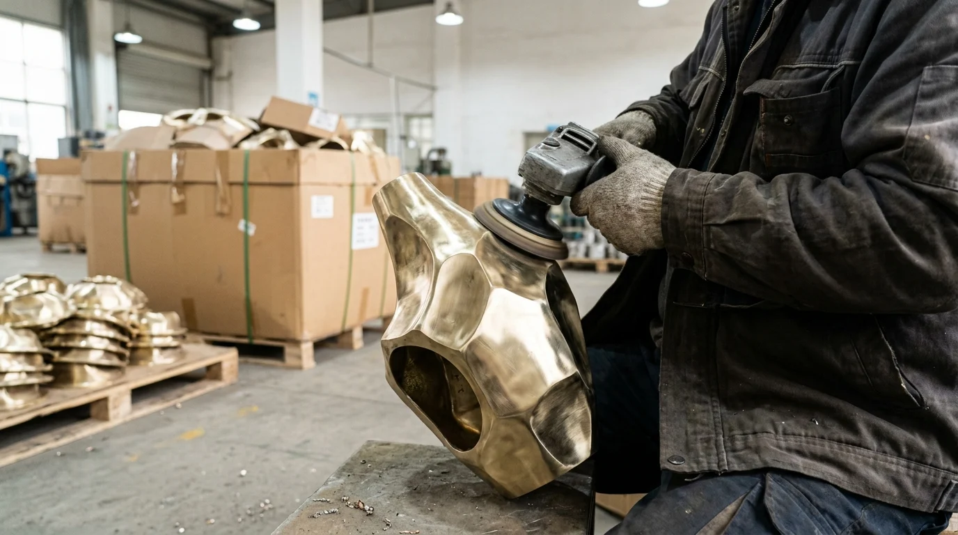
Base material properties and part topography act as the primary cost drivers in surface finishing. The intricate interaction between an alloy's metallurgical hardness, its thermal conductivity, and the workpiece's physical shape dictates cycle times, abrasive consumption, and the ultimate yield rate.
Aluminum, stainless steel, brass, zamak, and plated parts
Different metals respond to abrasive friction in fundamentally different ways. Aluminum alloys (such as 6061 or 6063) polish rapidly due to their relative softness but possess high thermal conductivity, making them highly susceptible to heat distortion and surface smearing if wheel speeds are poorly managed. Conversely, stainless steel (e.g., 304 or 316 series) demands high wheel pressure and aggressive cutting compounds. Polishing stainless steel typically requires substantially longer cycle times than brass, yet it yields superior long-term durability for exterior components.
Brass remains a preferred material for high-end decorative lighting due to its excellent machinability and rapid progression to a high-luster finish. Zamak (zinc alloy) die castings, frequently used for complex brackets and finials, present unique challenges. While Zamak requires less time for initial stock removal, the process is highly sensitive; it must remove flash without breaching the dense outer skin, as exposing sub-surface porosity will inevitably cause blistering during subsequent electroplating.
| Material | Typical Pre-Polish Ra (µm) | Relative Polishing Time Index | Primary Defect Risk |
|---|---|---|---|
| Aluminum (Extruded) | 0.8 - 1.2 | Baseline | Heat distortion, smearing |
| Brass (Cast/Machined) | 1.2 - 1.6 | Moderate | Over-polishing of sharp details |
| Stainless Steel (304) | 1.5 - 2.0 | High | Heat tinting, rapid abrasive wear |
| Zamak (Die Cast) | 0.6 - 1.0 | Low | Exposing subsurface porosity |
*Note: Relative Polishing Time Index values are illustrative internal estimates categorized into qualitative tiers.
Fixture shapes with the highest polishing risk
Geometry dictates the accessibility of the polishing wheel and heavily influences the defect rate. Workpieces featuring deep internal recesses, sharp internal corners with radii under 5 mm, and thin-walled extrusions under 1.5 mm in thickness carry the highest polishing risks. These specific measurements serve as common illustrative guidelines for high-risk geometries rather than strict universal standards.
Deep recesses cause uneven wheel pressure and restrict the flow of liquid polishing compounds, resulting in inadequate reflection in shadowed areas. Thin-walled geometries are prone to warping under the mechanical pressure and localized heat generated by sisal and cotton buffs, often leading to unrecoverable scrap.
How material and geometry influence process selection
The intersection of material hardness and component geometry ultimately governs the selection of the polishing machinery. Flat architectural lighting panels permit the use of high-speed, pass-through flatbed polishing machines, which can achieve exceptionally high processing rates.
In contrast, ornate brass chandeliers or complex cast aluminum sconces require multi-axis articulation to ensure the polishing wheel remains perpendicular to the undulating surface. This geometric complexity limits throughput to single-digit units per hour, dictating a choice between highly skilled manual labor or advanced automated systems capable of adapting to complex contours.
Efficient Process Routes for Mirror Finish Polishing
A systematic, multi-stage approach to surface refinement is essential to eliminate the subsurface damage left by casting, stamping, or CNC machining. Attempting to bypass intermediate abrasive steps inevitably leaves micro-scratches that manifest as optical distortion once the final luminaire is plated or illuminated.
Deburring, grinding, sanding, and polishing sequence
The standard progression for achieving a mirror finish moves methodically from coarse stock removal to ultra-fine color buffing. The sequence typically begins with deburring and grinding using 120-grit ceramic or zirconia abrasive belts to remove parting lines and heavy machining marks. The surface is then refined through progressive sanding stages—usually 240, 400, 600, and up to 800-grit.
Once the surface reaches a uniform 800-grit scratch pattern, the polishing phase commences. This involves heavy cutting with stiff sisal wheels and aggressive tripoli compounds, followed by intermediate buffing. The final stage utilizes soft, loose-stitched cotton wheels paired with fine rouge (aluminum oxide or chromium oxide) to achieve the previously defined surface roughness targets, pulling a deep, flawless luster from the metal.
Manual polishing, robotic polishing, and hybrid workflows
Manual polishing relies heavily on operator skill and tactile feedback, making it suitable for low-volume, highly complex decorative components. However, manual processes suffer from fatigue-induced inconsistency over a production shift. Robotic polishing cells solve this by utilizing 6-axis articulated arms and force-compliance end effectors. These automated systems maintain exact, programmed pressure against the contact wheel, adapting seamlessly to complex contours to ensure consistency over a production shift.
Many modern manufacturers adopt hybrid workflows. In these setups, robotic cells handle the vast majority of the heavy cutting and intermediate sanding—where consistency and pressure are paramount—while human operators perform the final color buffing and intricate touch-ups, leveraging human visual acuity to ensure the mirror finish meets aesthetic standards.
Controls that reduce haze, orange peel, waves, and drag marks
Surface defects such as haze, orange peel, waves, and drag marks are direct results of poor process control. Orange peel often occurs when excessive wheel pressure generates localized heat that exceeds the specific alloy's thermal threshold, causing the metal to micro-yield and suffer thermal distortion. Waves are typically caused by inconsistent feed rates or uneven manual pressure.
To mitigate these issues, manufacturers must implement strict spindle speed controls. Optimal true surface speeds (peripheral speeds) vary by material but generally range from 25 to 40 meters per second (m/s), or roughly 5,000 to 8,000 surface feet per minute (SFPM). It is a common technical error to specify this merely as RPM; the actual machine RPM must be carefully calculated based on the specific wheel diameter to achieve and maintain these target surface speeds. Furthermore, automated, precisely timed application of liquid polishing compounds prevents the wheel from running dry, which is the primary cause of drag marks and micro-burning on sensitive alloys.
Quality Control, Compliance, and Surface Protection
Validating a mirror finish requires rigorous metrology and environmental testing to ensure the surface not only meets aesthetic criteria but also withstands subsequent chemical processing and the end-use environment. Robust quality control frameworks prevent costly late-stage failures in the manufacturing cycle.
Measurable acceptance standards for mirror finishes
While visual inspection under controlled, high-intensity lighting (typically regulated between 1,000 and 1,500 lux at the inspection bench) remains a standard practice, objective metrology is critical for scalable production. Profilometers are deployed to measure Ra and Rz (mean roughness depth), while digital gloss meters verify reflectivity against a calibrated standard.
By utilizing statistical process control (SPC) and establishing clear numerical thresholds for these metrics, manufacturers can effectively manage process drift. A well-optimized polishing line should aim to maintain a final-stage reject rate below 2% (an illustrative internal benchmark), ensuring that only geometrically and optically perfect parts proceed to plating or assembly.
Coating compatibility, plating adhesion, and corrosion resistance
A polished surface must be chemically pristine before it undergoes physical vapor deposition (PVD) coating, electroplating, or clear lacquering. Residual polishing compounds—composed of greases, tallows, and abrasive dust—act as barrier layers that cause catastrophic adhesion failure. Consequently, robust ultrasonic cleaning protocols utilizing alkaline detergents are mandatory.
To verify surface readiness and coating integrity, finished components must pass the cross-hatch adhesion test (ISO 2409). Furthermore, to guarantee longevity in humid or coastal environments, the final plated or coated parts are subjected to neutral salt spray testing (ISO 9227). Premium architectural lighting components are typically required to withstand a minimum of 96 hours of continuous salt spray without exhibiting signs of base metal corrosion or coating delamination.
| QC Parameter | Measurement Tool | Target Value / Threshold | Applicable Standard |
|---|---|---|---|
| Surface Roughness | Stylus Profilometer | Ra < 0.05 µm | ISO 4287 |
| Specular Gloss | Gloss Meter (20° angle) | > 95 GU | ISO 2813 |
| Coating Adhesion | Cross-cut Tester | Class 0 (No peeling) | ISO 2409 |
| Corrosion Resistance | Salt Spray Chamber | > 96 hours to first rust | ISO 9227 |
Batch traceability and supplier documentation
Maintaining strict lot control ensures accountability across the supply chain. Manufacturers and their polishing partners must implement batch traceability systems that link finished components back to specific polishing shifts, abrasive batches, and operator IDs. Suppliers should routinely provide certificates of compliance (CoC) detailing the inspection metrics of each lot.
This level of documentation is not merely an internal quality tool; it is increasingly required for international compliance and risk mitigation. Robust traceability aligns with global trade standards and supply chain integrity frameworks, ensuring that manufacturers can swiftly isolate and recall defective batches without jeopardizing their entire distribution network.
In-House, Automated, or Outsourced Polishing Decisions
Determining the optimal polishing strategy—whether to keep the process in-house, invest in automation, or outsource to specialized vendors—requires a comprehensive total cost of ownership (TCO) analysis.
Key Takeaways
- Specify mirror finishes with measurable targets such as Ra < 0.05 µm and gloss above 95 GU at 20 degrees instead of using subjective terms like “shiny.”
- Separate decorative mirror requirements from functional optical reflector requirements because their roughness limits, testing methods, and cost drivers are different.
- Relax bare-metal polishing targets when electroplating or PVD will provide the final leveling and reflectivity, so the process does not waste cycle time.
- Group SKUs by material, geometry, and required polishing pressure to reduce changeovers and avoid the 15% to 20% throughput loss common in high-mix production.
- Reference surface texture standards such as ISO 4287 on technical drawings to align designers, quality teams, equipment operators, and external suppliers.
- Use robotic polishing equipment when consistent pressure, path control, and repeatability are needed for high-volume lighting fixture production.
Frequently Asked Questions
What roughness level defines a true mirror finish for lighting fixtures?
A premium mirror finish typically requires Ra below 0.05 µm, or about 2 microinches. Higher roughness scatters light and can make the surface appear hazy instead of sharply reflective.
How should manufacturers measure mirror finish quality?
Use both surface roughness and gloss measurements. A common premium target is Ra < 0.05 µm and gloss above 95 GU at a 20-degree measurement angle.
Do all lighting components need a full mirror polish?
No. Decorative housings, optical reflectors, commercial trims, and parts later coated by plating or PVD may need different finish levels. Over-specifying mirror polish can add unnecessary cost and cycle time.
When can bare-metal polishing targets be relaxed?
Targets may be relaxed when a leveling electroplate or high-gloss PVD coating will create the final reflective surface. The polishing specification should match the complete finishing route, not only the bare substrate.
Why does SKU complexity reduce polishing throughput?
Frequent changes in geometry, material, polishing pressure, wheels, and robot programs increase downtime. Facilities with many SKUs can see throughput drop by 15% to 20% without batching and standardization.